MicroLED Fine Pitch: The Physics of Direct-View Sub-Millimeter Emissive Walls
Direct-view light emitting diode (DV-LED) technology has moved from outdoor stadiums into executive boardrooms, network control centers, and high-end broadcast sets. By replacing conventional liquid-crystal matrix stacks with microscopic self-emissive gallium-nitride (GaN) crystals, MicroLED delivers infinite native contrast, true zero-lux black levels, and wide color gamuts that exceed DCI-P3 standards.
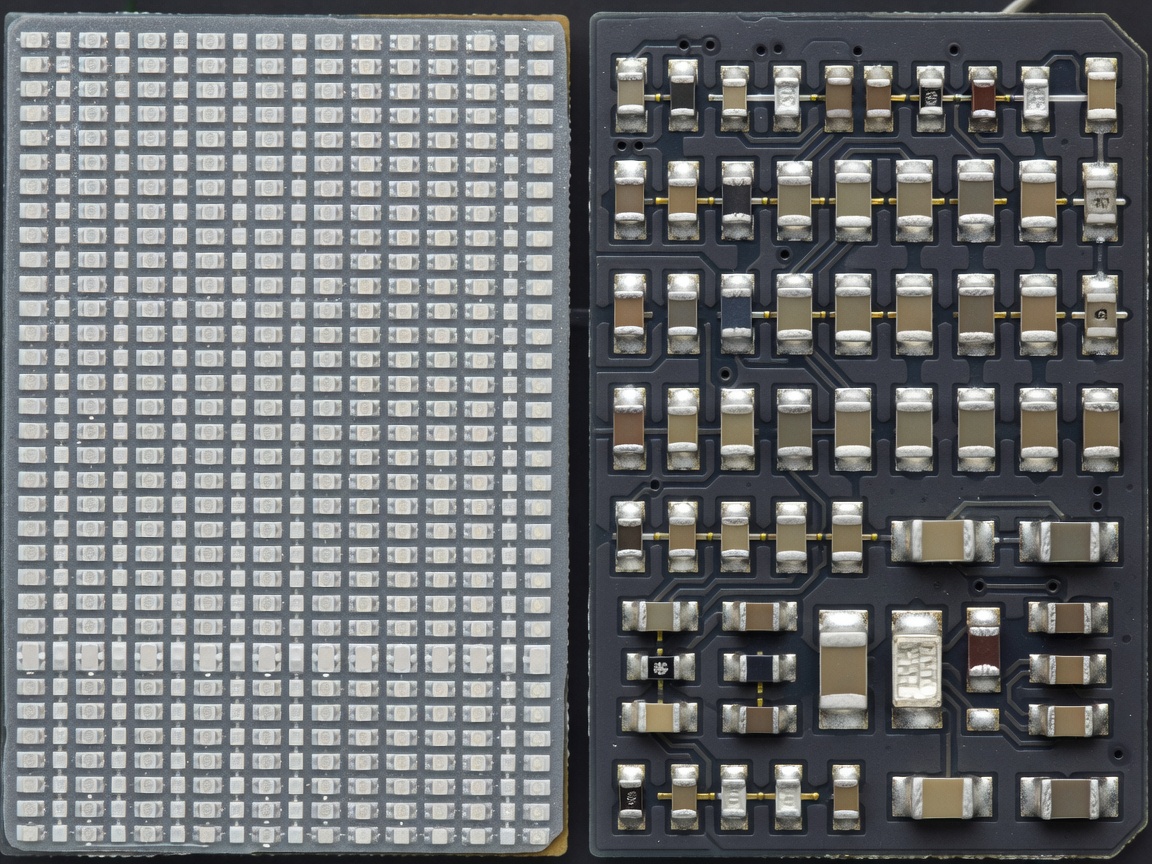
Packaging Topologies: SMD vs. COB vs. GOB
The core distinction in modern fine-pitch LED video hardware lies in the diode packaging architecture. Selecting the appropriate packaging directly influences durability, optical fill factor, and viewing angles:
- Surface Mounted Diode (SMD): Traditional approach where individual red, green, and blue diodes are packaged together in a tiny surface mount cup and soldered to the printed circuit board. While cost-effective, SMD displays below P1.5 are fragile. Cleaning personnel or passing pedestrian traffic can shear corner diodes off the edge of cabinet seams.
- Chip-on-Board (COB): Bare inorganic LED dies are mounted directly onto the PCB substrate without intermediate packaging cups. The entire cabinet module is then coated with an optical epoxy resin seal. COB provides high mechanical impact resistance (IK08 rated), excellent thermal dissipation into the board substrate, and protection against moisture and static discharge.
- Glue-on-Board (GOB): A hybrid manufacturing technique where standard SMD panels receive an automated polyurethane conformal pour. While providing enhanced impact protection, it does not achieve the optical fill factor or thermal dissipation of genuine COB microLED.
Pixel Pitch Optics and Visual Resolving Limits
In digital signage engineering, Pixel Pitch denotes the center-to-center distance between adjacent pixels, denoted in millimeters (e.g., P0.9, P1.2, P1.5). The human eye has a visual acuity limit of approximately 1 arcminute (1/60th of a degree). When the angular subtense of an individual pixel is smaller than this threshold, the viewer perceives a smooth, continuous image rather than an individual diode grid.
The standard baseline formula for determining comfortable viewing distance without seeing diode structure is:
For a mission-critical emergency command room where operators sit 2.4 meters from the primary data wall, a display with P1.2 pitch or smaller is recommended to ensure small geographic symbols, telemetry fonts, and 1-pixel vector boundaries remain fully legible without diode aliasing.
Optical Fill Factor and Black Level Contrast
A critical metric often omitted from consumer marketing is the Optical Fill Factor—the percentage of cabinet surface area occupied by active light emitters versus passive black background. In high-density MicroLED cabinets, microscopic diodes occupy as little as 5% to 10% of the panel surface. The remaining 90% is filled with proprietary non-reflective matte black resin.
This massive black ratio delivers contrast ratios exceeding 1,000,000:1 without localized halo artifacts common to Mini-LED backlit LCD televisions. When a pixel turns off in a MicroLED canvas, absolute zero light is emitted, allowing deep shadow details and high dynamic range content to be reproduced accurately even in bright broadcast environments.